Measuring Force with ShapeLog’s ShapeSense Select

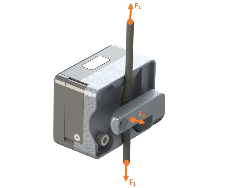
I have had long conversations about ShapeLog’s ShapeSense Select (Select) only to later realize that an important feature (THE most important feature, really) is not understood. The sensor doesn’t just measure motion. It also measures force! When the Select is slipped onto a cable or belt an arm on the UST redirects the cable such that it is no longer in a straight line. The image above illustrates this subtle but important feature. As force is transferred through the cable (F1) there is a proportional force (F2) detected by the Select.
A calibration is used to define the relationship between the actual Force (F1) imparted onto the weight stack and the force sensor signal generated from the force on the Select arm (F2). If you were paying attention in physics class you might recall that force is a function of both the mass and how much it is accelerated, or Force = mass * acceleration. Therefore during the calibration process the weight stack is held steady so that the only acceleration on the weights is from gravity, a known constant.
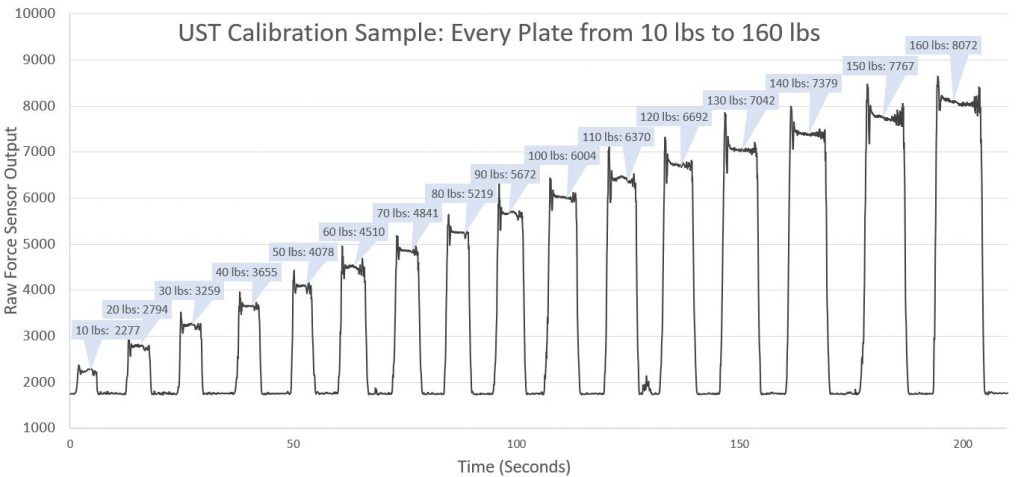
As an illustration I will show the raw force sensor values at a sequence of known force values ranging from 10 lbs-f to 160 lbs-f. In each case the weight was lifted and then head still for about 2 seconds:

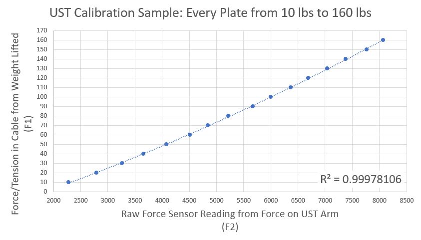
As you can see in the scatter plot below there is a clear correlation between F1 and F2. Generally, four or five calibration points is sufficient but in this exercise we did each and every possible setting (all 16 weight plates from 10 to 160 lbs) to share a more detailed look under the hood:

I hope you enjoyed this review of the fundamentals of how our ShapeSense Select measures force. Feel free to post a comment if you have any questions or suggestions for the next peek into the “ShapeLog Lab”.